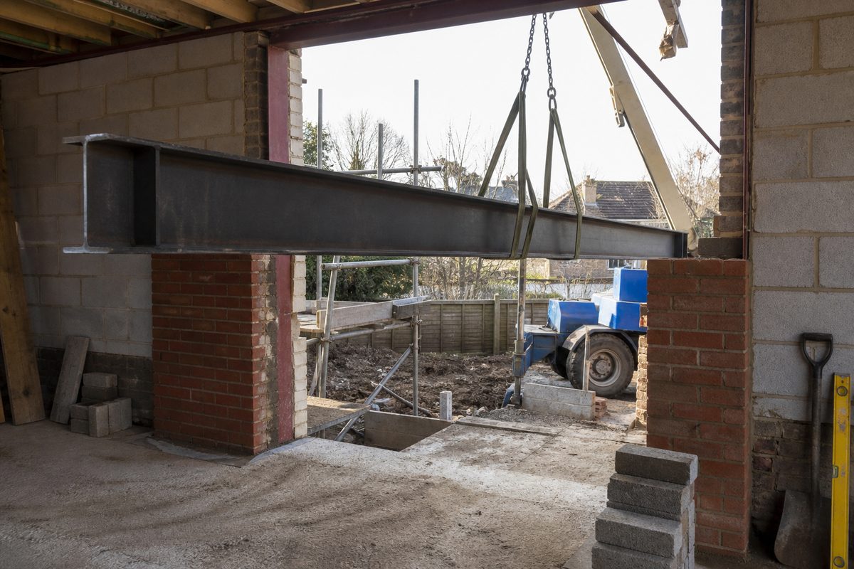
A 6m opening does not determine an RSJ size. The answer depends on what bears on the beam, the load width, lateral restraint, support condition and permitted movement.
Measure the right span
Record the clear opening and both supports separately. Your engineer determines the effective span; our calculators use support-centre distance. The ordered steel length is another dimension, set by the bearing or connection detail. Do not use a calculator input as a cutting instruction.
A 6m calculation, not a beam recommendation
Suppose a simply supported 203×133×25 UB spans exactly 6m between support centres and carries a total uniform service load of 12 kN/m including its own weight. With Iₓ = 2340 cm⁴ and E = 210,000 N/mm², the elementary model predicts 41.21 mm deflection. A selected L/360 comparison target would be 16.67 mm. Neither number checks strength, buckling, bearings or fire resistance. The assumed 12 kN/m is not a default domestic design load.
The calculation is δ = 5wL⁴/(384EI), using N and mm. You can reproduce it in the deflection calculator and compare sections in the beam size tool.
Source: British Steel Universal Beams datasheet, 21 July 2026. The shared section table and methodology lists the exact inputs used by our tools. These properties are not safe load ratings.
Delivery access can change the fabrication proposal
For a 6m opening, the ordered item may be longer than the clear opening once its actual support detail is included. Check the route, unloading arrangement and space for handling before fabrication. If a single piece cannot be installed, a splice is a design decision with its own connection detail; it cannot be improvised from an online suggestion. Send access constraints to the engineer and fabricator early enough to coordinate the issued drawing.
Why the deflection result changes so quickly
For the same total uniform load and section, increasing the model span from 4 m to 6 m multiplies the maximum moment by (6/4)² = 2.25. The calculated deflection is multiplied by (6/4)⁴ = 5.0625.
| Model span | Total uniform load | Maximum moment | Calculated deflection |
|---|---|---|---|
| 4 m | 12 kN/m | 24 kNm | 8.14 mm |
| 6 m | 12 kN/m | 54 kNm | 41.21 mm |
This explains why a section shown in an example for a shorter opening cannot simply be carried across to a longer one. The illustrative 6 m result also exceeds its selected L/360 comparison value of 16.67 mm. Neither the target nor these assumed loads define the requirements for your building.
Resolve depth, connections and access together
A deeper option may reduce movement in the simple model but affect finished headroom. A fabricated connection can take space beyond the bare flange width. A multi-piece arrangement introduces a connection whose location and behaviour need design. Discuss these constraints together rather than finding the lightest table row first and checking everything else later.
Ask for a coordinated drawing showing the steel arrangement and the intended floor or ceiling level. Obtain the complete fabricated weight and handling requirements from the responsible parties. If the access proposal changes, send that change back before fabrication proceeds.
Questions for the design meeting
Explain whether an uninterrupted opening is essential or whether the layout allows another structural arrangement. Identify roof or floor members that may deliver concentrated reactions and the positions of proposed supports. Ask what investigations are needed into the existing building below those supports.
Leave the meeting with an agreed arrangement and a named person responsible for each outstanding question. The section choice will depend on that design. Keep the final design revision with the quotations so that scope and geometry remain comparable.
Prepare a useful engineering brief
Provide measured plans, joist directions, floor and wall construction, storeys above, any roof reactions, proposed opening dimensions and photographs of the support locations. Flag chimneys, columns or other concentrated loads. Explain ceiling-height constraints, access for delivery, finish requirements and the jurisdiction for approvals.
Ask for a complete drawing and calculation package identifying the beam, grade, supports, connections and temporary works responsibilities before obtaining fabrication quotes.
What still needs a design check
A calculated deflection is only one part of a design. Load combinations, steel grade, buckling restraint, shear, connections, bearings, masonry, vibration and fire resistance also matter. Point loads, cantilevers and continuous beams require a different model. The engineer must establish the effective span and loads from the actual building; a clear opening measurement is not sufficient.
Structural work must be designed by a chartered structural engineer and receive the applicable Building Control approval. This article has not received an independent engineering review.